DIY PCBs with Solder Mask
January 17, 2014
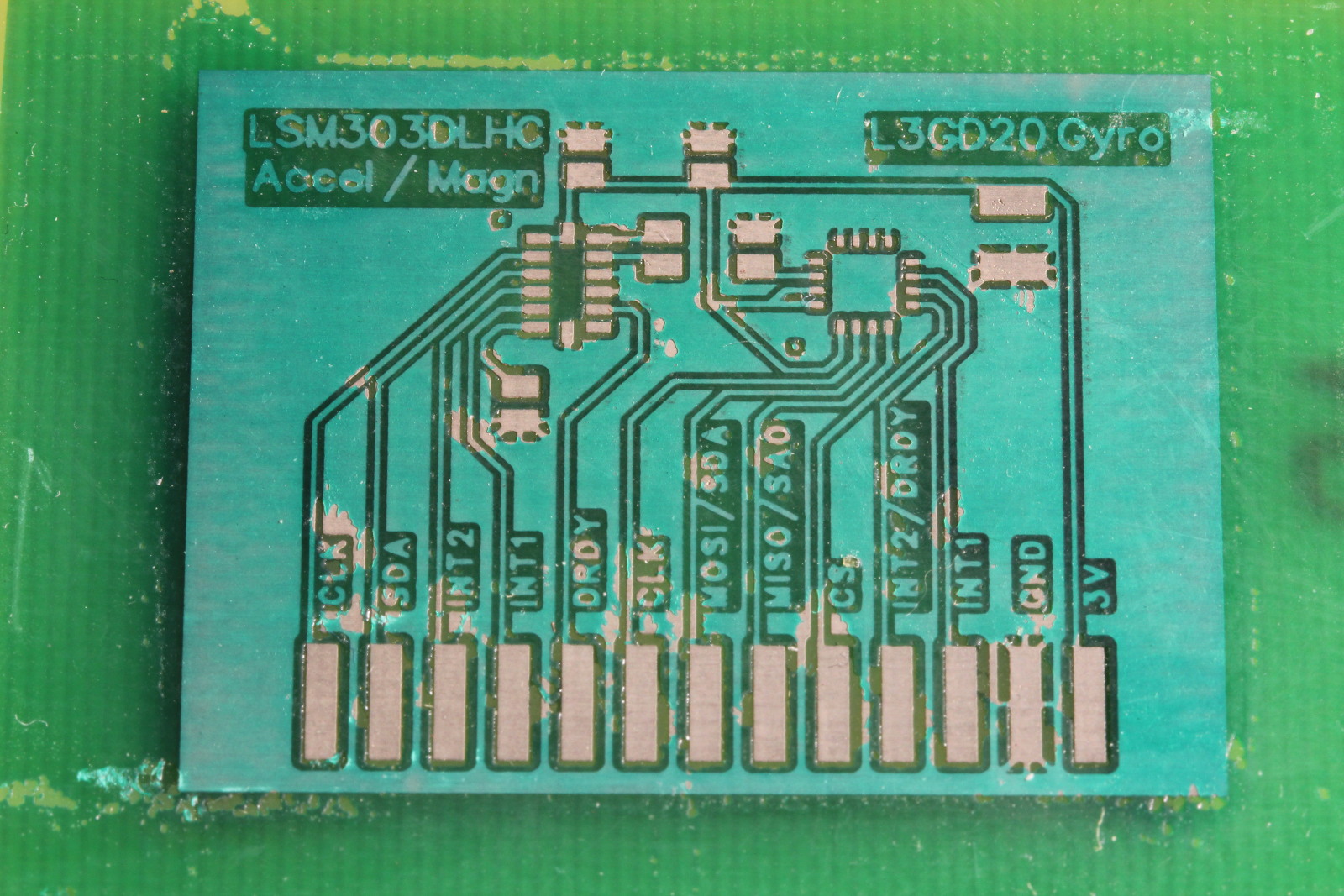
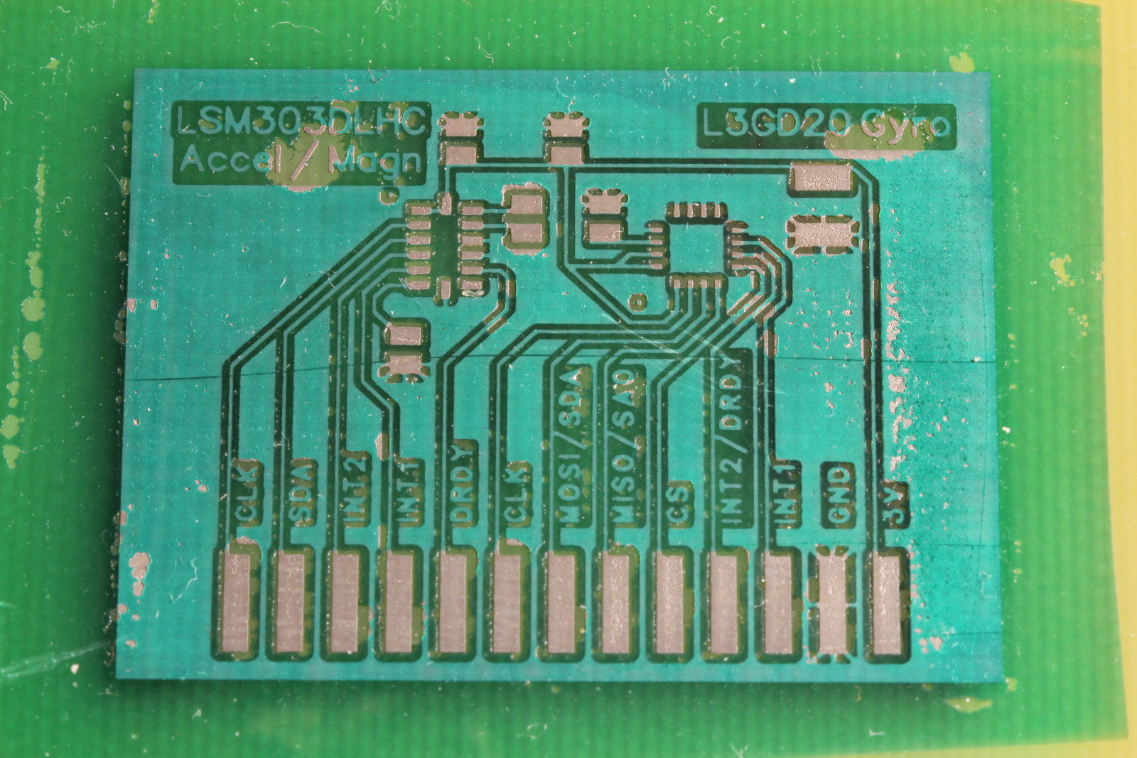
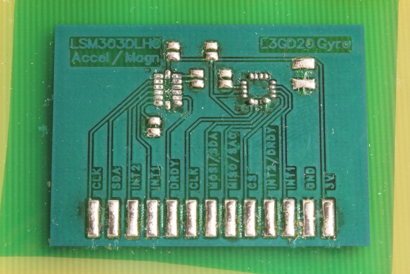
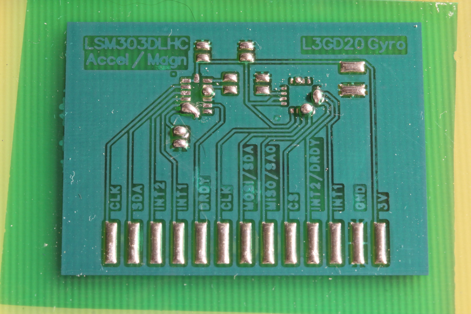
I’ve managed to get decent solder masks on my home made PCBs. The dry film variety has worked best for me, with liquid masks being difficult to apply consistently. To perfect my process I used a small gyro / accelerometer / magnetometer breakout PCB that I designed around a year ago. Here’s the end result:
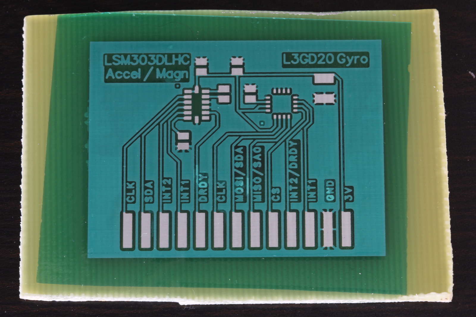
It’s not perfect — there are some spots with delamination — but the result is usable and very functional. It works just like the professional stuff. It tolerates abuse from an iron at 375C without damage. It sticks well and doesn’t scratch easily.
It took about eight failures, due to various problems, before I got to this point. I’m using Dynamask 5000 Dry Film Solder Mask. It’s sold in giant rolls, but small amounts can be purchased through eBay (search for “dry film solder mask”) for about $7 per square foot.
My process:
- Etch and tin plate the PCB (per my earlier blog post, but don’t sand the PCB to it’s final shape until after the solder mask is done.)
- Cut a piece of solder mask to size. It should be big enough to cover all of the copper, but not hang out past the edge of the PCB. If it hangs out, it can gum up the laminator.
- Make a 10% alcohol solution in water. I used SLX Denatured Alcohol from a local hardware store. Wet the entire surface of your PCB with it, using a q-tip. Don’t flood the board, but there needs to be a film over everything. This helps prevent air bubbles when you laminate.
- Peel the protective film off of the solder mask, place it on the PCB, and press the leading edge onto the PCB so it won’t slip around. Run it through the laminator at a low temperature two or three times.
- Let it sit for 30 minutes.
- Expose. With my UV lamp from MG Chemicals, this takes 10 minutes.
- Let it sit for 30 minutes.
- Remove the other protective film.
- Develop with half a gram of sodium carbonate per 12oz of water. It takes about five minutes to develop. Gently brush to remove the unexposed mask.
- Expose for 30 minutes.
- Bake at 145C for 30 minutes.
As I mentioned earlier, it took many attempts before I got a useable mask. Here are the problems I encountered:
Bubbles under the mask. If you follow the datasheet you’re supposed to use a vacuum laminator, but that’s outside the realm of a hobbyist. Little pockets of air will get trapped when using a hot roll laminator or an iron. I first tried using water to prevent air pockets, but it didn’t help much. Adding a bit of alcohol helped, perhaps the alcohol slightly “melts” into the uncured solder mask. Bubbles still occur, but there are fewer of them and they don’t usually break when you develop the mask. Without the alcohol your bubbles will break and yield an ugly surface:
Blotchy or satin sheen on the mask. This happens when the developer is too strong. I found 1 gram of sodium carbonate per 12oz of water to be too strong, and half a gram to be just right. This might change based on temperature — my stuff was all at around 70F.
Don’t forget to bake the board at the end. The final cure requires both UV exposure and the baking process, otherwise the mask will not fully harden. Even if you will use solder paste and reflow the board, you should still bake the board before doing that. You can easily gouge the mask while placing parts with tweezers.
I noticed that the flux in Chipquik’s SMD291SNL lead-free paste (Sn 96.5 / 3 Ag / 0.5 Cu) was very aggressive and would creep under the solder mask. Even without a solder mask, their flux will do a little damage to tinned copper. I have not had any problems with other solder pastes and I currently use Kester EP256 leaded paste.
Chipquik paste:
Kester paste:
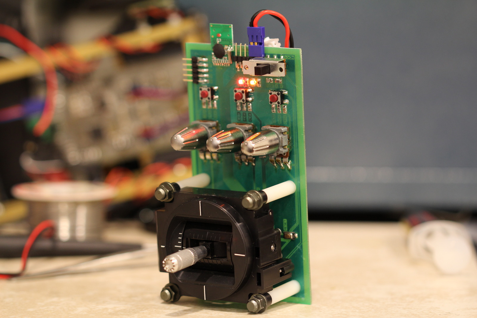
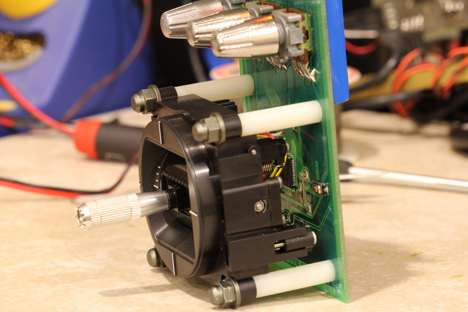
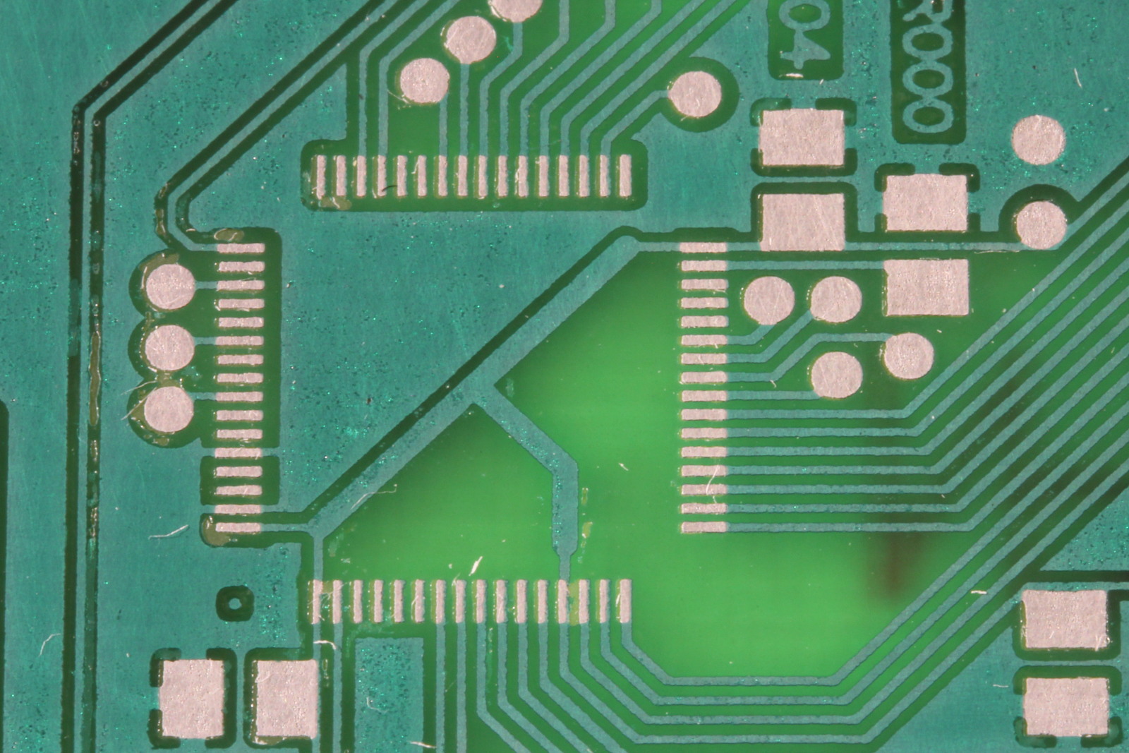
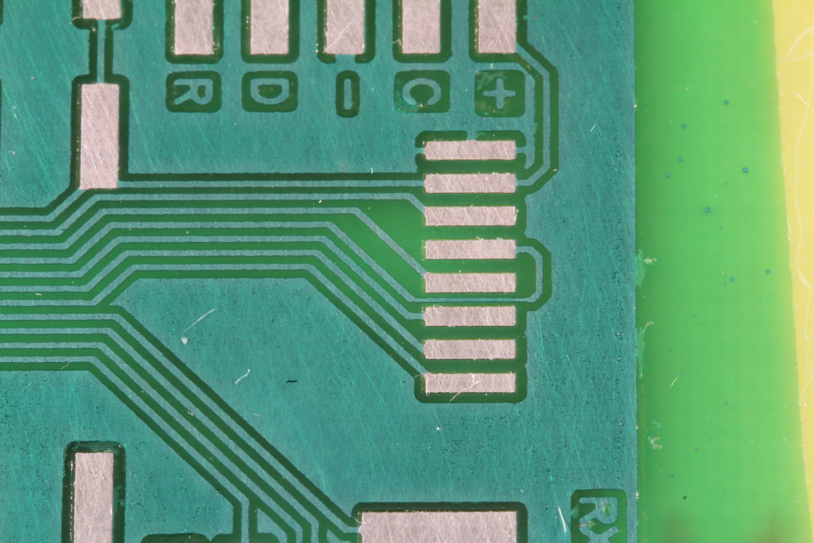
After getting the process figured out I decided to make a simple 2.4GHz transmitter for use with my robots. The PCB is below. The ugly looking ground fill is due to an overexposed photomask which allowed the etchant to slightly damage the surface.
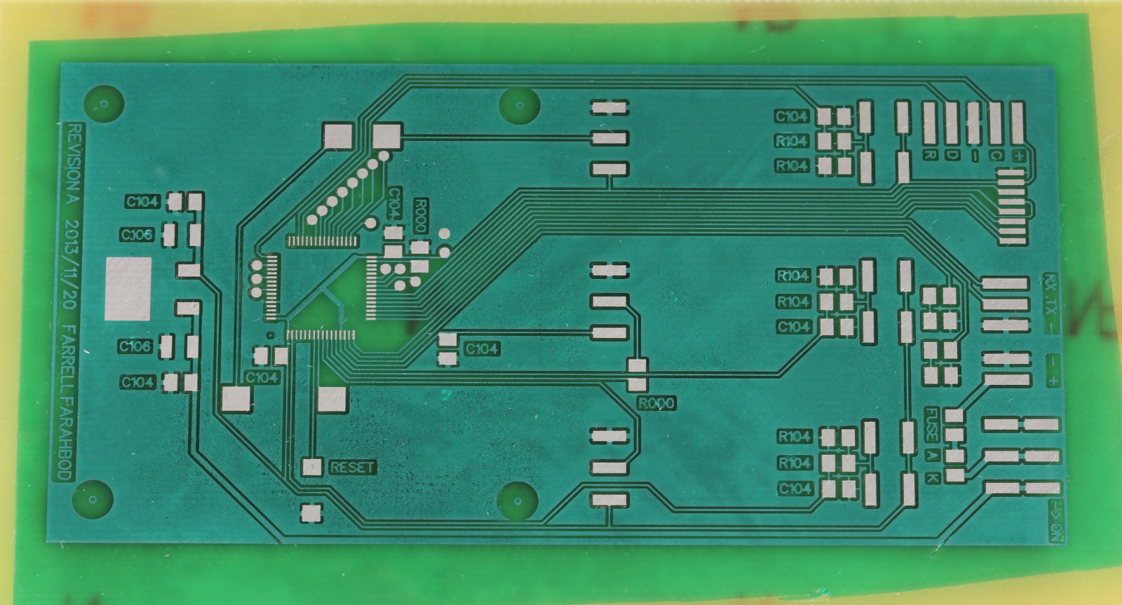
It turned out well. Imperfections only appear if you look up close.
I think the finished project turned out very well.