Building a Balancing Robot from Start to Finish

Almost three years ago I made my first balancing robot but it didn't perform very well. A few months ago I decided to give it another shot and record videos of the whole process from start to end. The end result was a robot that could balance very well, didn't drift very much, and was fun to drive around.

The first part of this journey involved modifying a pair of RC hobby servos. I removed the pin on the output gear to allow for continuous rotation, and I also disabled the internal servo control circuitry. Four wires now exit each servo: two for power, and two for driving the H-bridge externally.

In the video below I show two ways to modify servos: the first way allowed the servo to still be controlled with a servo signal. The second way allowed for controlling the h-bridge externally so you have better control over the motor. I also explained some the theory behind the h-bridge and how to use PWM signals to control it. Lastly, I showed how to mount an RC airplane wheel to the servo so it can be used to power small robots.

Then I built a chassis for the balancing robot. Some 1/4" brass square tube was used to form the chassis. It was cut to length with a Dremel, deburred with some needle files, and soldered together. The end result was a strong chassis that was easy and cheap to build:

Next I needed a sensor module for determining the robot's orientation. I used a GY-86 10DOF sensor breakout board. The board contains an InvenSense MPU6050 gyroscope / accelerometer, a Honeywell HMC5883L magnetometer and a Measurement Specialties MS5611 barometer. Here's a video showing the first steps of how to interact with those sensors:

The readings from the gyro and accelerometer needed to be combined in order to reliably calculate the orientation of the robot. I used Madgwick's filter because it works very well and is easy to use. There are only two filter settings that require attention: the gain, and the sample frequency. To help visualize the sensor fusion, I also wrote a very basic Java program using the Java3D and jSerialComm libraries. It shows a 3D cube rotating based on the quaternion output of the filter.

With orientation detection and motor control done, it was time to add wireless control. I used some TI CC2500 2.4GHz RF Modules. The video below starts with a short demo driving the robot around with a crude proportional-only control loop. Then I briefly covered the CC2500 datasheet, with explanations of the state diagram, the chip status byte, and a few other aspects of the chip. Finally I showed TI's SmartRF Studio software which makes it very easy to generate correct register values for a variety of RF configurations.

By far the largest fraction of time spent on this project involved writing a program to visualize live telemetry data received from the robot over a Bluetooth link. Since this tool will be helpful for countless other projects, I spent a lot of time to make it as reusable and helpful as possible. Telemetry is received via UART (wired or Bluetooth SPP) and the data can be visualized as: line charts (time domain), line charts (frequency domain), histograms, and as simple dials/gauges. The dial visualization also shows some basic statistics: min, max, mean, and standard deviation.

The only task remaining was to write and tune a PID control loop for the balancing robot. This last video starts with a brief demo of how the robot performs with a tuned PID control loop. The balancing robot does not have any wheel encoders or other position feedback, so the only control loop inputs are the pitch of the robot and the throttle input from the user. Because of that, the robot can drift a little if it picks up speed, but even so, with a properly tuned PID control loop it performs fairly well.

To demonstrate how to develop a PID control loop I showed how the robot behaves with proportional-only control, then PI control, then full PID control. With all three steps I demonstrated what happens if the gain is set too low or too high. I also showed the telemetry waveforms during the entire tuning process so you can see in detail how things change along the way.

Source code for the firmware is available here:
https://github.com/farrellf/Balancing_Robot_Firmware/blob/master/main.c?ts=4

Source code for the telemetry viewer software is available here:
https://github.com/farrellf/TelemetryViewer

Setting Up a Raspberry Pi Web Server

I've been using a Raspberry Pi as a low-cost/low-power server for the past couple years. This post is my short collection of notes related to setting up a Pi as a web server with the classic "LAMP" stack (Linux, Apache, MySQL, PHP.)

Software

Raspbian https://www.raspberrypi.org/downloads/raspbian/
Win32DiskImager https://sourceforge.net/projects/win32diskimager/
TeraTerm https://ttssh2.osdn.jp/index.html.en
Swish-SFTP http://www.swish-sftp.org/

Prepare an SD Card

Unzip the Raspbian archive and use Win32DiskImager to write the .img to an SD card. To run Win32DiskImager, you might to Right Click -> Run as Administrator. When the write completes, place the SD card in the Pi and plug in ethernet and micro USB cables. There is no need for a keyboard, mouse or monitor.

Connect to the Pi via SSH

Use your router to figure out the Pi's IP address and optionally setup the router to assign the Pi a static IP address. Run TeraTerm and start a SSH connection to that IP address. The default username is "pi" and the default password is "raspberry".

Optionally change the hostname by replacing all instances of "raspberrypi" with a new hostname:

sudo nano /etc/hostname sudo nano /etc/hosts

Optionally change the username by replacing all instances of "pi" with a new username:

sudo -s nano /etc/passwd (change the username AND home dir) nano /etc/shadow nano /etc/group nano /etc/gshadow nano /etc/sudoers mv /home/pi /home/newusername passwd newusername shutdown -r now

Reopen TeraTerm and login with the new username and password.

Configure Raspbian and Install Software Updates

Run raspi-config to setup the OS:

sudo raspi-config Expand the filesystem Set boot options to "B1 Console" Optionally set internationalization options to "en_US" and set the timezone Finish and let it reboot

Install software updates:

sudo apt-get update sudo apt-get upgrade

Install and Configure Apache, MySQL and PHP

Install the web server software:

sudo apt-get install apache2 php5 mysql-server mysql-client sudo chown -R yourusername /var/www sudo chgrp -R yourusername /var/www ln -s /var/www/html ~/html

At this point it's all up and running. Going to the Pi's IP address in a web browser should reveal the default Apache page. That page is stored in /var/www/html/index.html, and also accessable through the link you made as ~/html/index.html. Assuming you want the web server to be public, you probably want to setup port forwarding on your router (TCP port 80) and use a domain name and dynamic DNS service so people can type in a .com instead of an IP that might change over time.

I use Google Domains. It's around $12/year for a .com and they include dynamic DNS service at no extra cost. Here's how to setup the dynamic DNS service they offer:

Login to https://domains.google.com/ In the rows of domain names, click on the DNS icon for the domain you want to setup In the Synthetic Records section, select Dynamic DNS For the subdomain, use "@" (without the quotes) for no subdomain (like when someones goes to yourdomain.com instead of www.yourdomain.com) Then make another record for the "www" (without quotes) subdomain Click on the > icon next to each record, then click View Credentials

You can use software like ddclient to notify Google when your IP changes, or you can keep things simple and just visit a specially-crafted URL periodically to keep Google up-to-date. I wrote a simple script to visit that URL and record it's response to a text file. Be sure to make the script executable:

nano ~/dns_update_script.sh wget https://username:password@domains.google.com/nic/update?hostname=yourdomain.com -qO dns_update_results.txt wget https://username:password@domains.google.com/nic/update?hostname=www.yourdomain.com -qO- >> dns_update_results.txt echo " Last run: `date`" >> dns_update_results.txt chmod +x ~/dns_update_script.sh

The script downloads the web pages to the text file (the first wget creates the text file, the second wget appends to the text file) and then I also append the current date and time to the text file.

Setup a cron job to run the script at the start of every hour:

crontab -e 0 * * * * ~/dns_update_script.sh

Using Virtual Hosts to Serve Multiple Domains

A single computer can serve multiple domains. Apache supports this and calls it a "Virtual Host." You can repeat the following steps for as many domains as needed:

sudo nano /etc/apache2/sites-available/yourdomain.conf <VirtualHost *:80> ServerName www.yourdomain.com ServerAlias yourdomain.com *.yourdomain.com DocumentRoot /var/www/yourdomain </VirtualHost> sudo mkdir /var/www/yourdomain sudo chown -R yourusername /var/www/yourdomain sudo chgrp -R yourusername /var/www/yourdomain ln -s /var/www/yourdomain ~/yourdomain sudo a2ensite yourdomain sudo service apache2 reload

Using Swish-SFTP to Copy Files to the Pi

After installing Swish-SFTP, there will be a "Swish" device listed in File Explorer > This PC. Double-click it, then choose "Add SFTP Connection" near the top of the window. After making a connection you can drag-and-drop files between Windows and the Pi.

That's it. You now have a web server that requires less than 5 watts of power to run, and occupies hardly any space in your home.

YouTube Video

I also made a YouTube video showing the process. In the video I did not cover Virtual Hosts.

Lattice MachXO2 Breakout Board HelloWorld with Diamond

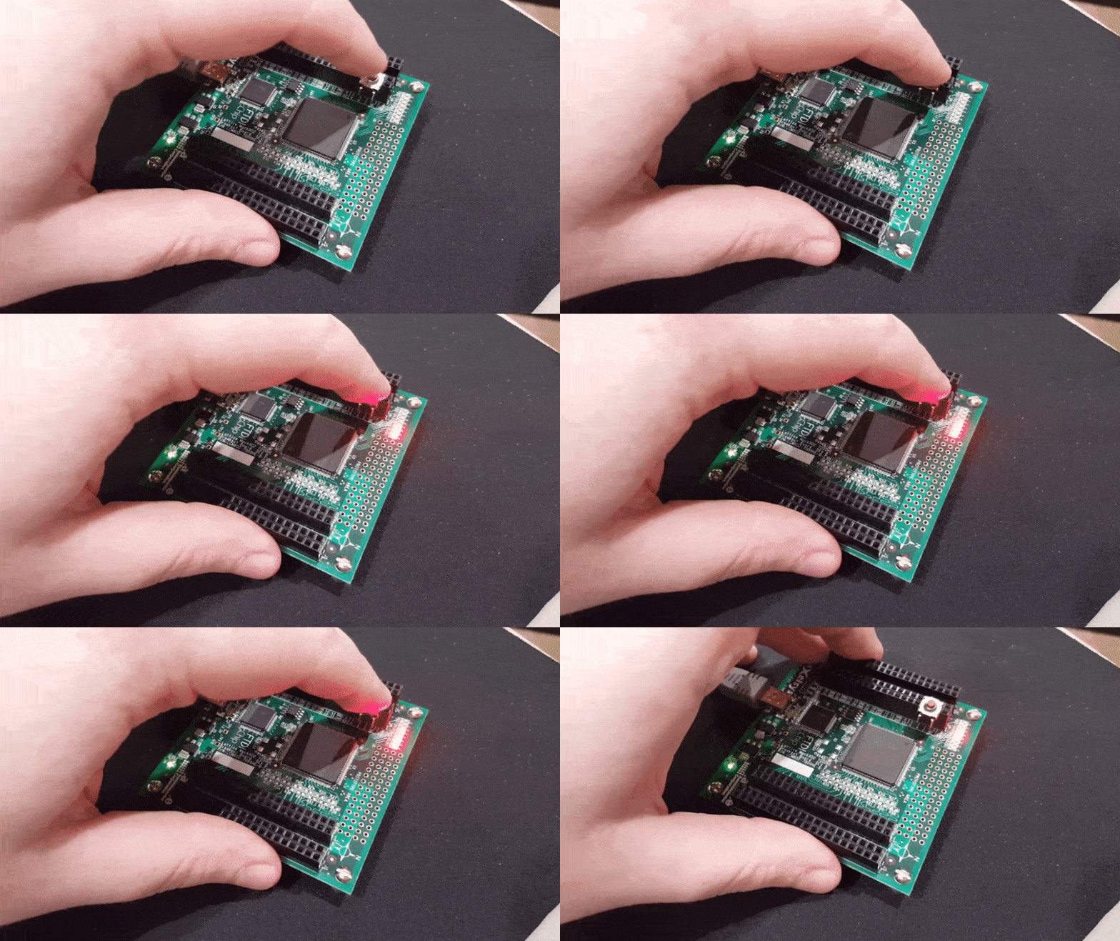
Lattice offers a cheap and simple development board for their MachXO2 FPGA. It's just a breakout board with an FPGA, a couple voltage regulators, and an FTDI FT2232 to handle the JTAG stuff. The board is around $25 - $30 from the usual suppliers (Mouser, DigiKey, etc.) This post is my collection of notes for the Lattice Diamond toolchain. I'll cover the basics of setting up a project, simulating it, programming it to Flash or SRAM, and introduce the embedded logic analyzer tool. To keep this post reasonably short, the project is intentionally trivial. A counter is created and setup to only count up when the user holds down a push button. The 8 MSbits of the count are displayed on the 8 LEDs of the development board.

Some Useful Links

http://www.latticesemi.com/en/Products/DevelopmentBoardsAndKits/MachXO2BreakoutBoard.aspx
Product page for the development board.

http://www.latticesemi.com/Products/FPGAandCPLD/MachXO2.aspx
Product page for the MachXO2 FPGA

http://www.latticesemi.com/view_document?document_id=43937
User's Guide for the development board. It has the schematic, BoM, and a general explanation of the board.

http://www.latticesemi.com/latticediamond
Lattice Diamond (IDE) product page. You'll need to register with Lattice. It's free. Register with a valid e-mail address because they email your license file.

http://www.latticesemi.com/view_document?document_id=51417
Lattice Diamond 3.6 Tutorial. A great introduction that walks you through the basics of the IDE.

http://www.latticesemi.com/view_document?document_id=51419
Lattice Diamond 3.6 User's Guide.

http://www.latticesemi.com/view_document?document_id=51424
Lattice Reveal 3.6 User's Guide. Reveal is their embedded logic analyzer tool.

http://www.latticesemi.com/~/media/LatticeSemi/Documents/DataSheets/MachXO23/MachXO2FamilyDataSheet.pdf
Lattice MachXO2 datasheet. It covers the usual stuff: the family of chips, what's possible, overview of how things work, electrical characteristics, timing, etc.

http://www.latticesemi.com/view_document?document_id=39080
Lattice MachXO2 sysCLOCK PLL Design and Usage Guide. You'll need to instantiate the internal RC oscillator for most projects, and that's covered on pages 28-30.


There are lots of other useful documents, but the ones linked above will get things started. Be sure to check out the Documentation sections on the MachXO2 and Diamond product pages.

Install Lattice Diamond

  1. Download Diamond from the link above. Run the installer and let it install all drivers.
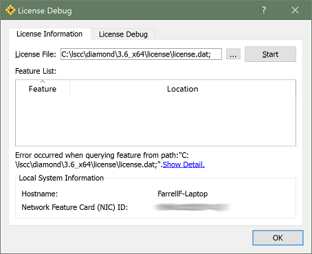
  2. Open Diamond. The first time you launch it, there will be two errors regarding a missing license file. Click OK both times.
  3. When the License Debug window pops up, go to the License Information tab. Note your NIC ID near the bottom of that tab.
  4. Go to http://www.latticesemi.com/Support/Licensing/DiamondAndiCEcube2SoftwareLicensing/DiamondFree.aspx and enter your NIC ID (without the colons between bytes.)
  5. Close the License Debug window by clicking OK.
  6. A "license.dat" file will be emailed to you, place it inside C:\lscc\diamond\3.6_x64\license
  7. Restart your PC. Yes, this really seems to be required. If you don't, Diamond will repeatedly fail to find the license file.

Create a New Project

  1. Open Diamond.
  2. Create a new project:
    File > New > Project Next > give it a name and choose a better project location > Next > Next Pick your device. The XO2 Breakout Board has a LCMXO2-7000HE-4TG144C Next > Next > Finish

Write the Code

  1. Create a top file:
    File > New > File Verilog Files > name it "top" > New
  2. Write some code:
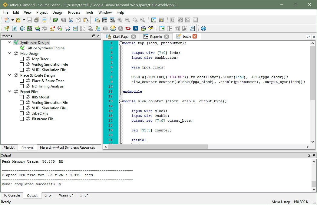
    module top (leds, pushbutton); output wire [7:0] leds; input wire pushbutton; wire fpga_clock; OSCH #(.NOM_FREQ("133.00")) rc_oscillator(.STDBY(1'b0), .OSC(fpga_clock)); slow_counter counter(.clock(fpga_clock), .enable(pushbutton), .output_byte(leds)); endmodule module slow_counter (clock, enable, output_byte); input wire clock; input wire enable; output reg [7:0] output_byte; reg [31:0] counter; initial begin output_byte = 8'b11111111; counter = 32'b0; end always @(posedge clock) begin if(enable == 1'b1) begin counter <= counter + 1'b1; output_byte <= ~counter[31:24]; end end endmodule
  3. Synthesize the code to make sure there are no errors. A green checkmark indicates success.
    Process tab > double-click on Synthesize Design

Simulate

  1. Create a testbench file:
    File > New > File Verilog Files > name it "testbench" > New
  2. Write some code that simulates a user holding down the pushbutton for one second:
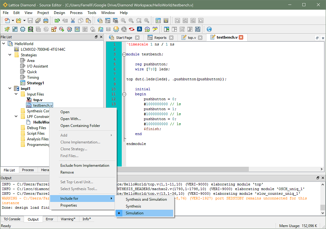
    `timescale 1 ns / 1 ns module testbench; reg pushbutton; wire [7:0] leds; top dut(.leds(leds), .pushbutton(pushbutton)); initial begin pushbutton = 0; #1000000000 // 1s pushbutton = 1; #1000000000 // 1s pushbutton = 0; #1000000000 // 1s $finish; end endmodule
  3. Mark top.v for "synthesis and simulation" and mark testbench.v for "simulation"
    File List > impl1 > Input Files > top.v > right-click > Include for > Synthesis and Simulation File List > impl1 > Input Files > testbench.v > right-click > Include for > Simulation
  4. Run the simulation. It will take a while to run because three seconds of time will be simulated. Most simulations run for just a few microseconds, but this is a long run due to the intentionally slow behavior of the LEDs.
    Tools > Simulation Wizard Next > give it a name > Next > Next > Next > Next > Finish Aldec Active-HDL will run but defaults to pausing the simulation after 1us. Simulation > Run > OK
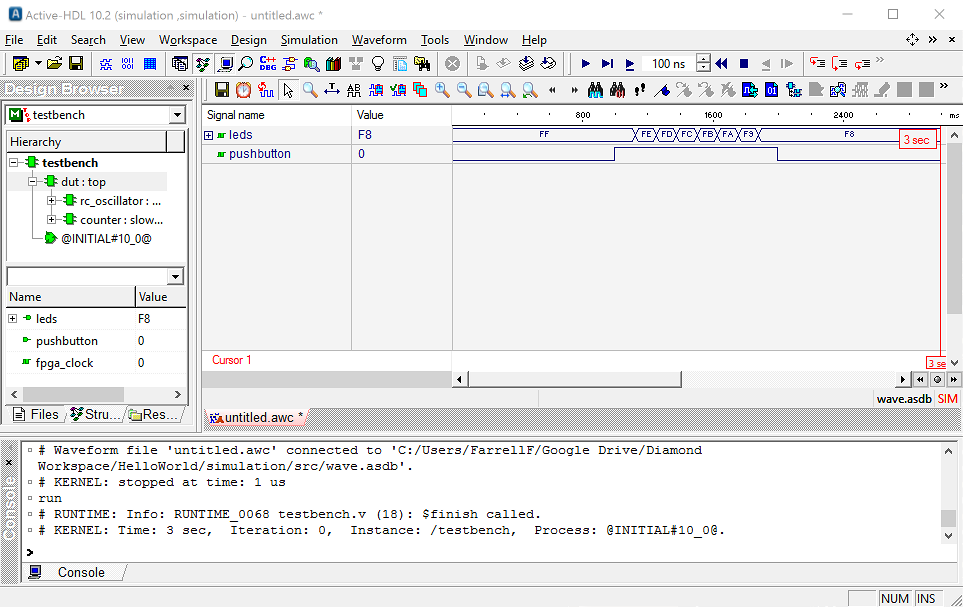
  5. Zoom the waveform to see all of it. Observe the LEDs slowly changing over time. Note that it looks like a count-down but in real life it will look like a count-up because the LEDs are wired active-low on the PCB.
    Waveform > Zoom to Fit

Assign Pins and Generate the Bitstream File

  1. Re-synthesize the code.
    Process tab > double-click on Synthesize Design
  2. Open the Spreadsheet View and assign pin numbers:
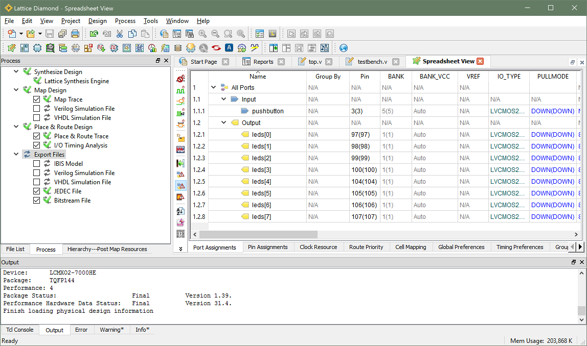
    Tools > Spreadsheet View Assign the "leds" nets to the pins for the LEDs. (Pin numbers are on page 13 of the dev board user guide.) Assign the "pushbutton" net to pin 3.
  3. If you want to look at reports, enable the ones you want:
    Process tab > Map Design > check "Map Trace" Process tab > Place and Route Design > check "Place and Route Trace" Process tab > Place and Route Design > check "I/O Timing Analysis"
  4. Generate a "JEDEC File" if you want to program to flash, and/or generate a "Bitstream File" if you want to program to SRAM.
    Process tab > Export Files > check "JEDEC File" Process tab > Export Files > check "Bitstream File" Double-click on Export Files. This will generate the files and perform all prerequisite functions.

Program to Flash or SRAM

  1. Program to flash:
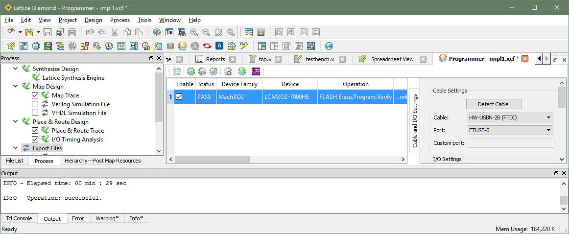
    Tools > Programmer Detect Cable Pick the "...Lattice FTUSB Cable Interface A..." device > OK Device = "LCMXO2-7000HE" File Name = your .jed file (The .jed file will be in the "impl1" folder inside your project folder.) Design > Program
  2. Optionally change to SRAM programming mode:
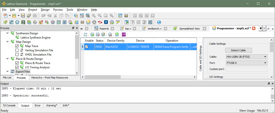
    Double-click below "Operation" Access Mode = Static RAM Cell Mode Operation = SRAM Erase, Program, Verify Programming File = your .bit file (The .bit file will be in the "impl1" folder inside your project folder.) OK Design > Program

Embed a Logic Analyzer

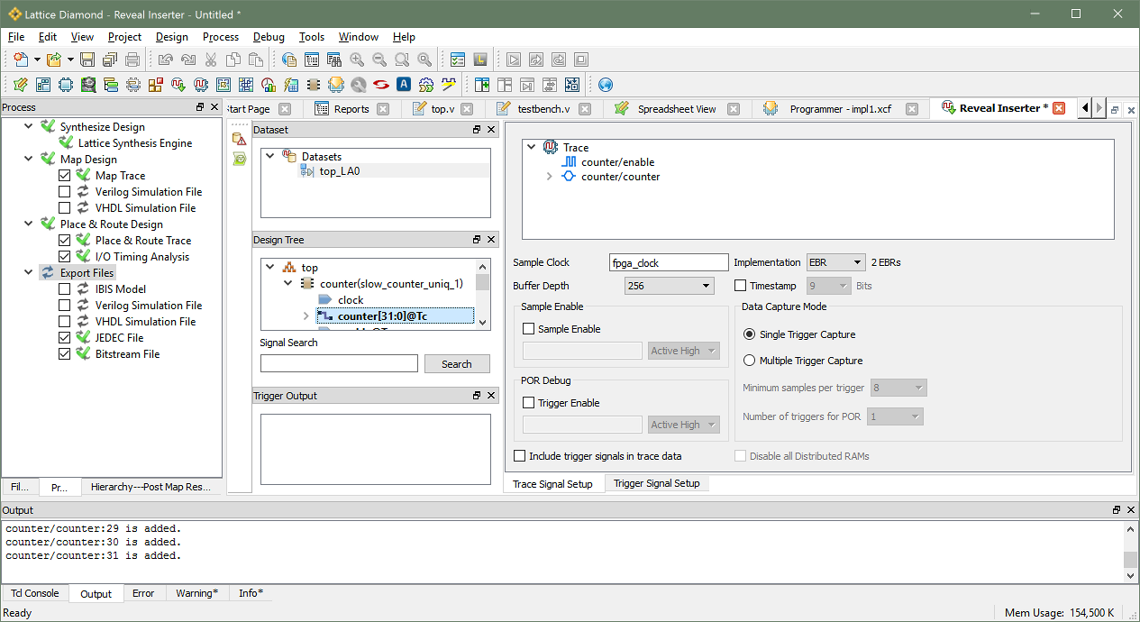
  1. Open Reveal Inserter and specify what signal(s) to "probe" and specify what signal will clock the logic analyzer. I'm probing the counter's enable signal (the pushbutton) and the counter's internal 32bit count. I'm clocking the logic analyzer with the 133MHz FPGA clock.
    Tools > Reveal Inserter Drag-and-drop any signals you want to probe from the Design Tree over to the Trace area of the Trace Signal Setup tab. Drag-and-drop your clock signal over to the Sample Clock box of the Trace Signal Setup tab.
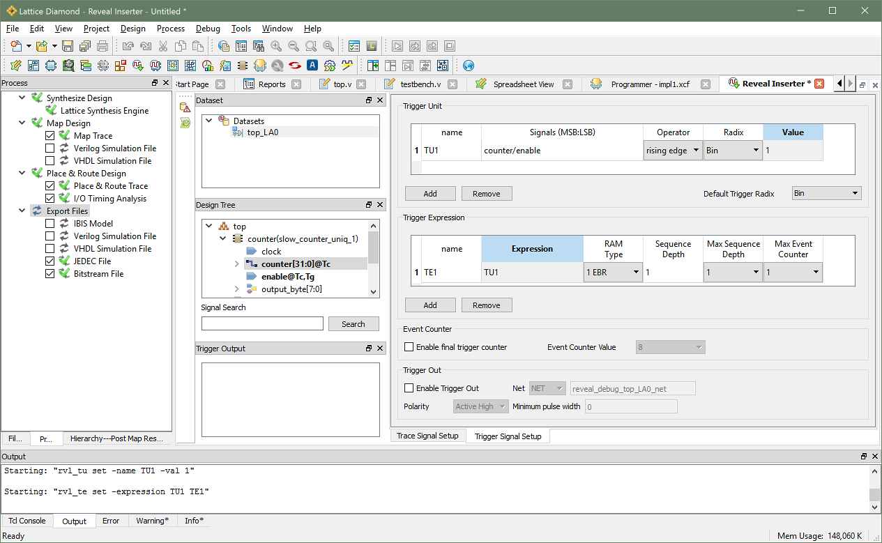
  2. Specify what signal(s) to trigger off of in the Trigger Unit section. Specify a trigger expression in the Trigger Expression section. I'm triggering off of a rising edge on the counter's enable signal. I don't need a complicated expression, so I just specify the trigger unit as the expression.
    Click on the Trigger Signal Setup tab In the Trigger Unit area: Double-click below Signals Choose the counter's enable signal, click the ">" button, click OK Set Operator to Rising Edge Set Value to 1 In the Trigger Expression: Set Expression to TU1
  3. Check for errors, then embed the logic analyzer into the project:
    Debug > Design Rule Check Look at the Output tab at the bottom of the window for "Design Rule Check PASSED." Debug > Insert Debug OK > Specify a filename for the Reveal project > Save
  4. Re-generate the JEDEC and/or Bitstream files, then re-program the FPGA:
    Double-click on "Export Files" in the Process tab. Tools > Programmer Design > Program

Use the Logic Analyzer

  1. Open and setup Reveal Analyzer:
    Tools > Reveal Analyzer Click "Create A New File" > give it a name Click "Detect" Click "Scan" Click "Browse" > pick the .rvl file you saved earlier > OK OK
  2. Start the logic analyzer:
    Click the Run icon (looks like a play symbol) next to Ready "Ready" will change to "Connecting" then "Running" It's now waiting for a trigger. Press the pushbutton to trigger it.
  3. You can zoom the waveform with Ctrl-scrollwheel.
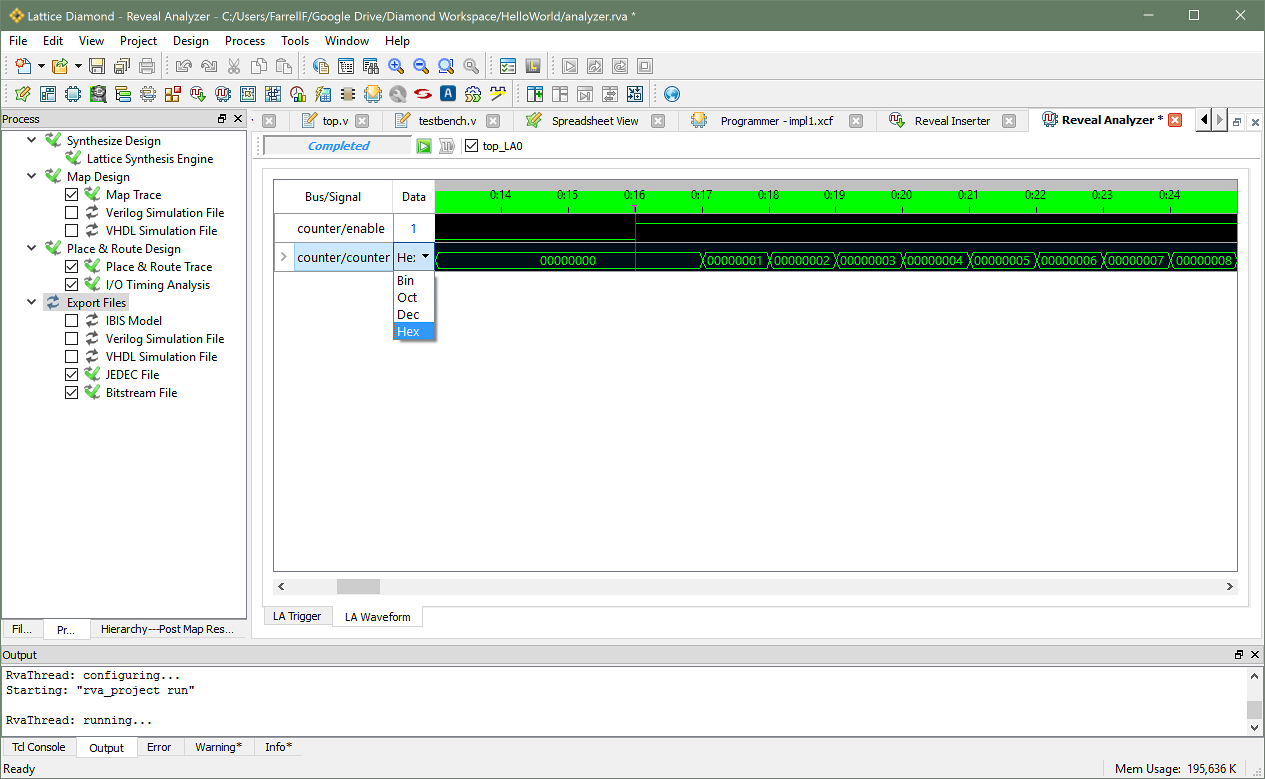
  4. You can change the radix of a multi-bit signal by clicking in the Data column.
  5. You can re-arm the logic analyzer by clicking the Run icon (play symbol) again.

YouTube Video

FTDI SPI Tutorial: LibMPSSE with Visual Studio 2015

FTDI is mostly known for their USB UART chips, but some of their higher-end ICs also have an “MPSSE” (multi-protocol synchronous serial engine) that can do SPI, I2C and JTAG. I made a YouTube video tutorial covering the basics of their SPI library for C. I thought I'd also write this post to summarize that video and provide its content in text form for easier referencing.

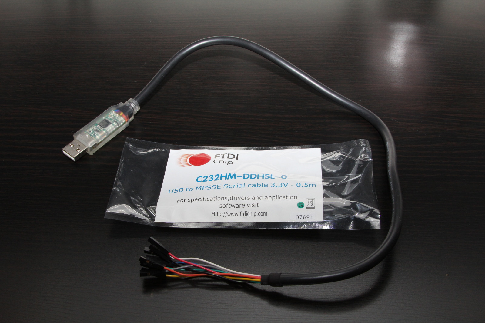
FTDI sells a ready-made USB adapter, it's part number C232HM-DDHSL-0. You can buy it from the usual suppliers (Mouser, DigiKey, etc.) for around $26 + shipping. It's essentially an FT232H broken out to 10 wires with female 0.1” connectors.

Some Useful Links

http://www.ftdichip.com/Products/Cables/USBMPSSE.htm
The product page for this USB adapter and some other ones.

http://www.ftdichip.com/Drivers/D2XX.htm
The D2XX driver you'll need to install. Windows will automatically install the VCP driver (UART driver) when you plug the cable in, but you need to manually install this D2XX driver if you want to use the cable for SPI/I2C/JTAG projects.

http://www.ftdichip.com/Support/Documents/DataSheets/Cables/DS_C232HM_MPSSE_CABLE.PDF
The datasheet for this USB adapter. It's got the schematic, a brief summary of what's possible, and tells you which color wire is used for what.

http://www.ftdichip.com/Support/Documents/AppNotes/AN_188_C232HM_MPSSE_Cable_in_USB_to_SPI-Interface.pdf
An App Note that provides a HelloWorld-level demo of their SPI library for C. It's a useful document, but their code isn't as clear as I'd like. They also did things the hard way (declaring a bunch of function pointers for the DLL) which is not needed if you will be using Visual Studio.

http://www.ftdichip.com/Support/Documents/AppNotes/AN_178_User_Guide_For_LibMPSSE-SPI.pdf
The User Guide for their SPI library for C. It documents all of the functions and data structures.

http://www.ftdichip.com/Support/SoftwareExamples/MPSSE/LibMPSSE-SPI/LibMPSSE-SPI.zip
The actual library and a simple demo project. This ZIP file contains the headers and the .lib file you will need to copy into your project.

Prepare a Visual Studio 2015 Project

  1. Open Visual Studio 2015, then create a new project:
    File > New > Project Templates > Visual C++ > Win32 Console Application Give the project a name, then click OK In the Application Wizard: click Next, then uncheck "Precomiled Header", then click Finish
  2. Remove some unneeded files from the project: stdafx.h, targetver.h, and stdafx.cpp
    In the Solution Explorer, right-click over each of those files > Remove > Delete
  3. Copy four files from FTDI's LibMPSSE-SPI zip file (linked above) into the Visual Studio project: ftd2xx.h, libMPSSE.lib, libMPSSE_spi.h, and WinTypes.h
    Those files are in LibMPSSE-SPI.zip > LibMPSSE-SPI > Release > samples > SPI > SPI Copy those four files into your Visual Studio project's folder. By default, that would be in: This PC > Documents > Visual Studio > Projects > YourProjectName > YourProjectName
  4. Tell Visual Studio about those four recently added files:
    In the Solution Explorer, right-click on Header Files > Add > Existing Item Select ftd2xx.h, libMPSSE_spi.h, and WinTypes.h, then click Add In the Solution Explorer, right-click on Resource Files > Add > Existing Item Select linMPSSE.lib, then click Add
  5. Fix an error in WinTypes.h: Replace "sys/time.h" with "time.h"
    Change line 5: Before: #include <sys/time.h> After: #include <time.h>

Minimalist Demo Program

By now the Visual Studio project is fully setup. You can starting using the API. Below is a simple demo program I wrote. It's communicates with an SPI gyroscope and displays X/Y/Z velocities on screen.

  1. The program starts by displaying information about each MPSSE "channel" that is available. An MPSSE channel is the part of the IC that can do SPI/I2C/JTAG protocols. Some FTDI ICs are UART-only, so they won't have any MPSSE channels. The USB adapter I'm using has one MPSSE channel. Some of their more advanced ICs have two MPSSE channels.
  2. The user will be asked to specify which MPSSE channel to use.
  3. The program will prepare that channel for SPI Mode 0 with a 1 MHz clock.
  4. The SPI gyro will be configured by writing to five of it's registers.
  5. Finally, an infinite loop is used to poll the gyro's X/Y/Z velocity registers. Those velocities are formatted and printed to the screen.
  6. The program can be closed by pressing Ctrl-C.
There are 1 channels available. Channel number: 0 Description: C232HM-DDHSL-0 Serial Number: 1637980 Enter a channel number to use: 0 x = -182, y = -395, z = -1157 x = -50, y = -14, z = -276 x = -351, y = -159, z = -1936 x = -211, y = -293, z = -190 x = -217, y = -310, z = -200 x = -232, y = -329, z = -177 x = -216, y = -301, z = -185 x = -239, y = -329, z = -167 x = -211, y = -304, z = -185 x = -215, y = -307, z = -209 x = -234, y = -285, z = -189 ...

Source Code

// red wire = 3v3 // black wire = ground // orange wire = sclk // yellow wire = mosi // green wire = miso // brown wire = cs #include <stdio.h> #include <Windows.h> #include "libMPSSE_spi.h" // a helper function for showing fatal error messages void print_and_quit(char cstring[]) { printf("%s\n", cstring); getc(stdin); exit(1); } int main(int argc, char **argv) { Init_libMPSSE(); FT_STATUS status; FT_DEVICE_LIST_INFO_NODE channelInfo; FT_HANDLE handle; // check how many MPSSE channels are available uint32 channelCount = 0; status = SPI_GetNumChannels(&channelCount); if (status != FT_OK) print_and_quit("Error while checking the number of available MPSSE channels."); else if (channelCount < 1) print_and_quit("Error: no MPSSE channels are available."); printf("There are %d channels available.\n\n", channelCount); // print out details for each MPSSE channel for (int i = 0; i < channelCount; i++) { status = SPI_GetChannelInfo(i, &channelInfo); if (status != FT_OK) print_and_quit("Error while getting details for an MPSSE channel."); printf("Channel number: %d\n", i); printf("Description: %s\n", channelInfo.Description); printf("Serial Number: %d\n", channelInfo.SerialNumber); } // ask the user to select a channel uint32 channel = 0; printf("\nEnter a channel number to use: "); scanf_s("%d", &channel); // open the MPSSE channel (get the handle for it) status = SPI_OpenChannel(channel, &handle); if (status != FT_OK) print_and_quit("Error while opening the MPSSE channel."); // init the channel (configure it) ChannelConfig channelConfig; channelConfig.ClockRate = 1000000; // 1 MHz channelConfig.configOptions = SPI_CONFIG_OPTION_MODE0 | SPI_CONFIG_OPTION_CS_DBUS3 | SPI_CONFIG_OPTION_CS_ACTIVELOW; channelConfig.LatencyTimer = 75; status = SPI_InitChannel(handle, &channelConfig); if (status != FT_OK) print_and_quit("Error while initializing the MPSSE channel."); // configure the gyro uint8 tx_buffer[6] = { 0x20 | (1 << 6) | (0 << 7), // first register is 0x20, bit6 high for auto-increment mode, bit7 low for write mode 0b01111111, // value for register 0x20 0b00101001, // value for register 0x21 0b00001000, // value for register 0x22 0, // value for register 0x23 0 // value for register 0x24 }; uint32 transferCount = 0; uint32 options = SPI_TRANSFER_OPTIONS_SIZE_IN_BYTES | SPI_TRANSFER_OPTIONS_CHIPSELECT_ENABLE | SPI_TRANSFER_OPTIONS_CHIPSELECT_DISABLE; status = SPI_Write(handle, tx_buffer, 6, &transferCount, options); if (status != FT_OK) print_and_quit("Error while configuring the gyro."); // enter an infinite loop that reads X/Y/Z velocities from the gyro while (1) { uint8 tx_buffer[7] = { 0x28 | (1 << 6) | (1 << 7), // first register is 0x28, bit6 high for auto-increment mode, bit7 high for read mode 0, // read register 0x28 0, // read register 0x29 0, // read register 0x2A 0, // read register 0x2B 0, // read register 0x2C 0 // read register 0x2D }; uint8 rx_buffer[7] = { 0 }; uint32 transferCount = 0; uint32 options = SPI_TRANSFER_OPTIONS_SIZE_IN_BYTES | SPI_TRANSFER_OPTIONS_CHIPSELECT_ENABLE | SPI_TRANSFER_OPTIONS_CHIPSELECT_DISABLE; status = SPI_ReadWrite(handle, rx_buffer, tx_buffer, 7, &transferCount, options); if (status != FT_OK) print_and_quit("Error while reading from the gyro."); int16 x = (rx_buffer[2] << 8) | rx_buffer[1]; int16 y = (rx_buffer[4] << 8) | rx_buffer[3]; int16 z = (rx_buffer[6] << 8) | rx_buffer[5]; printf("x = %+6d, y = %+6d, z = %+6d\n", x, y, z); } // this code will never be reached due to the infinite loop above, but you would normally want to end with this: Cleanup_libMPSSE(); return 0; }

YouTube Video

Servo Tester / 2.4GHz Spectrum Analyzer / Tetris Firmware

As promised in my previous post about this servo tester / spectrum analyzer / tetris implementation, I have uploaded the source code to my Servo Tester repository on GitHub. Check out the photos in that previous post if you'd like to see the work as it progressed over a few months of code refactoring and feature additions. I made a brief video clip to demonstrate the features of the firmware:

< Prev  3  Next >