Servo Tester / 2.4GHz Spectrum Analyzer / Tetris

Back in 2012 I started working with the STM32 line of microcontrollers and my first big project was a servo tester. That project worked out great and the tool I made has been in use for the last two years. Recently I decided to update the project and expand upon it. I added a color LCD with touchscreen, voltage and current sensing, a 2.4GHz spectrum analyzer, and for fun I decided to implement a simple version of Tetris. The end result:

It took quite a bit of work to get this project done. The prototype was a mess of jumper wires and breakout boards. I also started out with push buttons for the user interface but switched to using the touchscreen in an effort to keep things simple.

Here's a short video clip of me testing the Tetris game:

This project marked the first time I have ever had a PCB professionally fab'd. I was very relieved and pleased when everything worked perfectly with the first PCB revision. After I got the PCBs in the mail I checked them over, assembled one board, flashed the firmware... and it worked!

I bought a project box, Dremel'd and filed it to shape, then hot glued the electronics in place:

I'll post a video clip and the firmware within the next day or two.

A Complete STM32F0 Development Environment

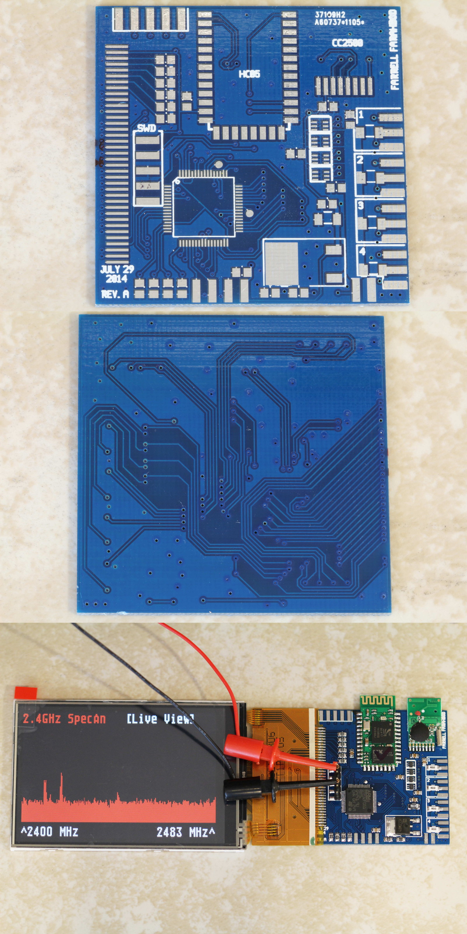
This post expands on (and updates) a few of my earlier posts about developing for the STM32F0 microcontroller. Some parts have become easier and I've found a few more useful ways to get things done. Some of the commands below assume a Debian-based Linux distribution, but should be reworkable for your particular setup.

Let's start by making some directories for the STM32 tools and projects:

$ mkdir ~/stm32 $ mkdir ~/stm32/projects

Installing the Toolchain

The GCC ARM Embedded package is a collection of utilities (compiler, assembler, libraries, debugger, etc.) that's maintained by ARM employees. It's available in the regular repositories, but you can use a PPA to get more up-to-date versions. OpenOCD facilitates communication between your PC and the ST-Link programmer. Install both tools:

$ sudo add-apt-repository ppa:terry.guo/gcc-arm-embedded $ sudo apt-get update $ sudo apt-get install gcc-arm-none-eabi libnewlib-arm-none-eabi libnewlib-doc gdb-arm-none-eabi openocd

There's currently a minor bug: those packages don't include the newlib-nano library. If you need newlib-nano you can manually install the GCC ARM Embedded package. Instead of using the above three commands, use these:

$ sudo apt-get install openocd ia32-libs $ cd ~/stm32 $ wget https://launchpad.net/gcc-arm-embedded/4.8/4.8-2014-q1-update/+download/\ gcc-arm-none-eabi-4_8-2014q1-20140314-linux.tar.bz2 $ tar -xjvf gcc-arm-none-eabi-4_8-2014q1-20140314-linux.tar.bz2 $ echo export PATH=$PATH:/home/username/stm32/gcc-arm-none-eabi-4_8-2014q1/bin >> ~/.bashrc $ source ~/.bashrc

Regardless of how you install GCC Arm Embedded, you'll also want the CMSIS and STM StdPeriph libraries:

$ cd ~/stm32 $ git clone https://github.com/szczys/stm32f0-discovery-basic-template.git $ cd stm32f0-discovery-basic-template/Libraries/ $ make

We're now ready to build and flash some firmware. I'll cover three ways to accomplish that: using the command line, using the Geany IDE, and using the Eclipse IDE.

Building and Flashing: From the Command Line

For a very simple workflow you can just use the command line to get everything done. Write your code in whatever editor you like, and use a Makefile to encapsulate all of the build, debugging and device programming commands.

My basic empty project is available as a zip file or through my stm32f0-empty-project repository on GitHub. Extract it to ~/stm32/projects/. It has a main() that just configures a GPIO and toggles it in an infinite loop. The f0lib/ directory contains my incomplete and unpolished collection of potentially reusable code. There's also a Makefile and configuration files for GDB and OpenOCD. Usage is trivial:

make compiles the firmware into an ELF and a BIN.
make install flashes the firmware to the STM32F0 with OpenOCD.
make clean deletes the ELF and BIN.
make debug_server, make debug_nemiver and make debug_cli are used for debugging. More on this in the debug sections below.

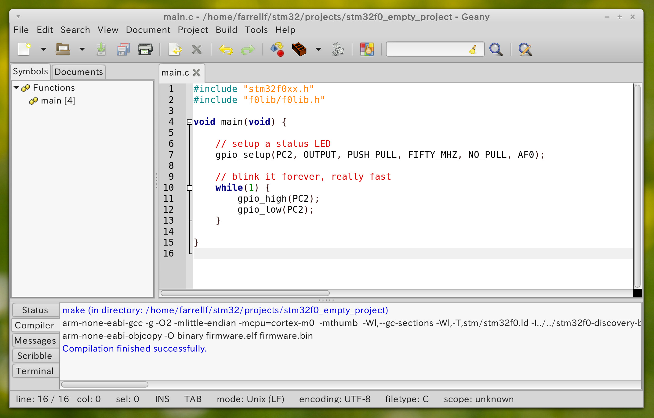
Building and Flashing: With the Geany IDE

Geany is a simple IDE and perhaps my favorite environment for programming in C. The IDE is essentially a text editor with a few extra features to support coding. It's minimalist and very fast. The only settings you need to change are the build commands. Go to Build > Set Build Commands. Configure them as compile = make clean, build = make, execute = make install. While this might sound weird, it makes the three build icons in the toolbar perfect for one-click actions instead of having to use the drop-down build menu.

Side note: if you're using Cinnamon or Gnome3 with a high-DPI display, the experimental GTK3 support in Geany gives you a beautiful high-DPI-friendly IDE. You'll have to build Geany from source with ./configure --enable-gtk3 && make && make install.

Building: With the Eclipse IDE

Many people prefer the Eclipse IDE. While I don't care for it's busy interface and relatively sluggish performance, there is a must-have plug-in that gives awesome annotated register views in the debugger. Start by installing the Eclipse and CDT packages, then install the GNU ARM Eclipse and EmbSysRegView plug-ins. Don't install Eclipse from the repositories -- the repo version of Eclipse is a few years old.

Download from https://www.eclipse.org/downloads/ Extract to ~/stm32 Open Eclipse Help > Install New Software > Work with > Kepler Programming Languages > C/C++ Development Tools Help > Install New Software > Add Name = GNU ARM Eclipse Plug-in Location = http://gnuarmeclipse.sourceforge.net/updates Select: Cross Compiler Support, Generic Project Templates, STM32Fx Project Templates, OpenOCD Debugging Support Help > Install New Software > Add Name = EmbSysRegView Plug-in Location = http://embsysregview.sourceforge.net/update Select: embsysregview (both components)

I only use Eclipse for debugging, so you might be better served by reading the GNU ARM Eclipse plug-in documentation. My way is a bit of a dirty hack to just get things working well enough to debug. Here's what I do:

File > New > C Project Executable > Empty Project > Cross ARM GCC > Next > Next Toolchain Path = ~/stm32/gcc-arm-none-eabi-4_8-2014q1/bin Finish Copy the contents of your project folder into the Eclipse project's folder. Then in Eclipse: Right click on project > Refresh Right click on project > Properties C/C++ General > Paths and Symbols > GNU C > Add > File system Navigate to: ~/stm32/stm32f0-discovery-basic-template/Libraries/CMSIS/Device/ST/STM32F0xx/Include OK > OK > Yes Right click on project > Properties C/C++ Build > Build Settings tab Uncheck “Use default build command” Uncheck “Generate Makefile automatically” Build command = make Build directory = ${workspace_loc:/your_project_name_goes_here} C/C++ Build > Behavior tab "Build (incremental build)" = leave it empty

Again: I only use Eclipse for debugging. If you actually want to do any development in Eclipse, don't do what I do.

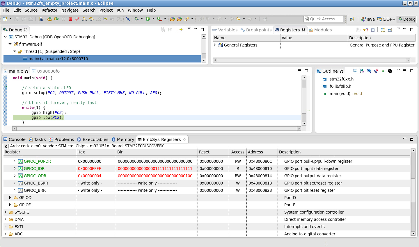
Debugging: With the Eclipse IDE

Having already prepared your project, now setup the debugging parts:

Right click on project > Debug as > Debug Configurations Double-click on GDB OpenOCD Debugging Name = STM32_Debug Debugger tab Uncheck “Start OpenOCD locally” GDB Client Setup Executable = arm-none-eabi-gdb Apply Close Window > Preferences C/C++ > Debug > EmbSys Register View Architecture = cortex=m0 Vendor = Stmicro Chip = stm32f051x Board = STM32F0DISCOVERY In a terminal in the project directory: make debug_server (Leave this running) Click on the debug drop-down in the toolbar > STM32_Debug > Yes Window > Show View > Other Debug > EmbSys Registers

You can now debug using step/next/etc. Double-click on registers in the EmbSys Registers tab to view their contents. It automatically updates as you step though code.

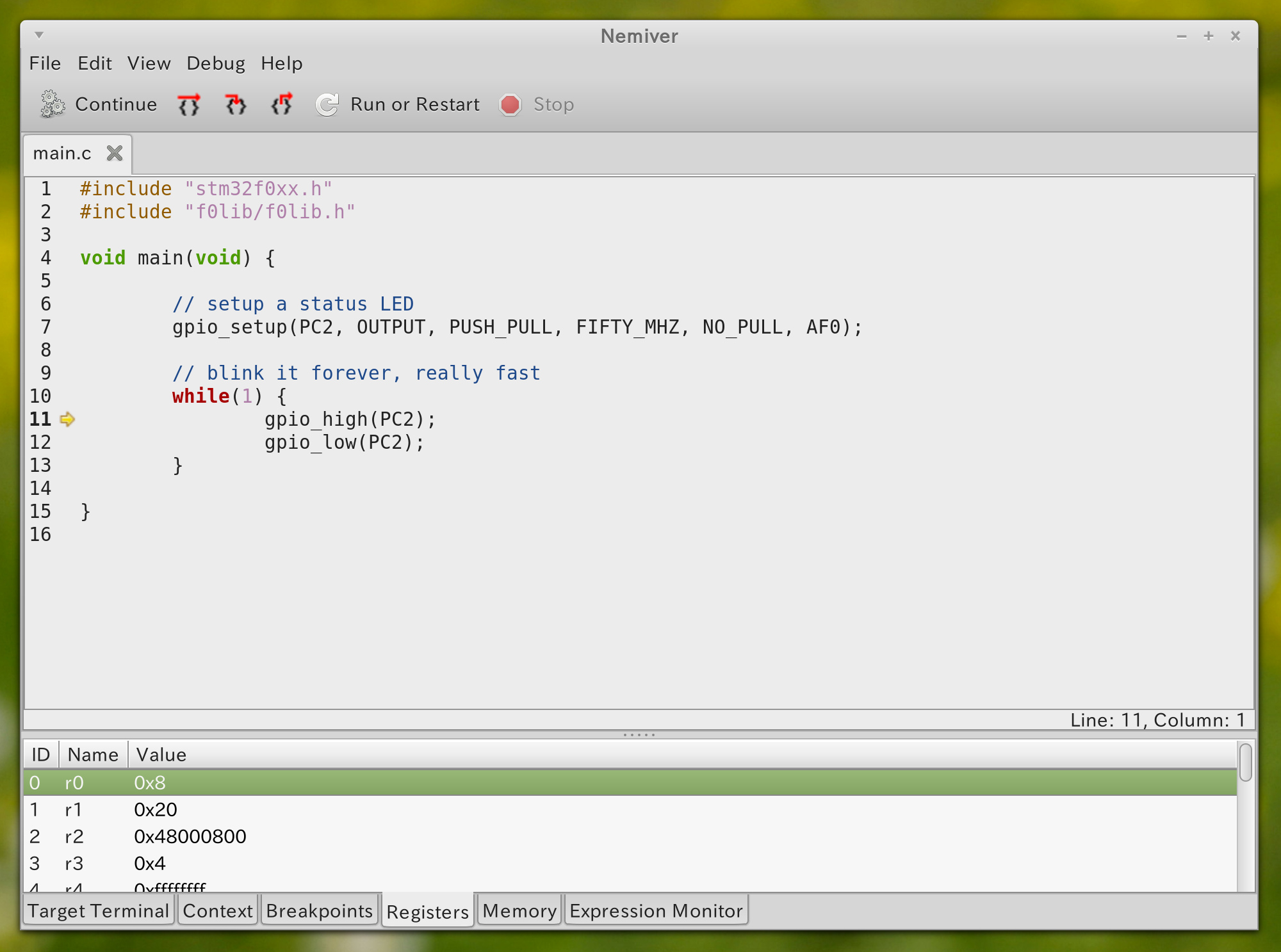
Debugging: With Nemiver

Nemiver is a fast and no-frills debugger. Using it with this project is trivial:

$ make debug_server $ make debug_nemiver

make debug_server will have to stay running for the duration of the debugging process, so run it in a separate terminal window. After closing Nemiver you can close the server with Ctrl-C.

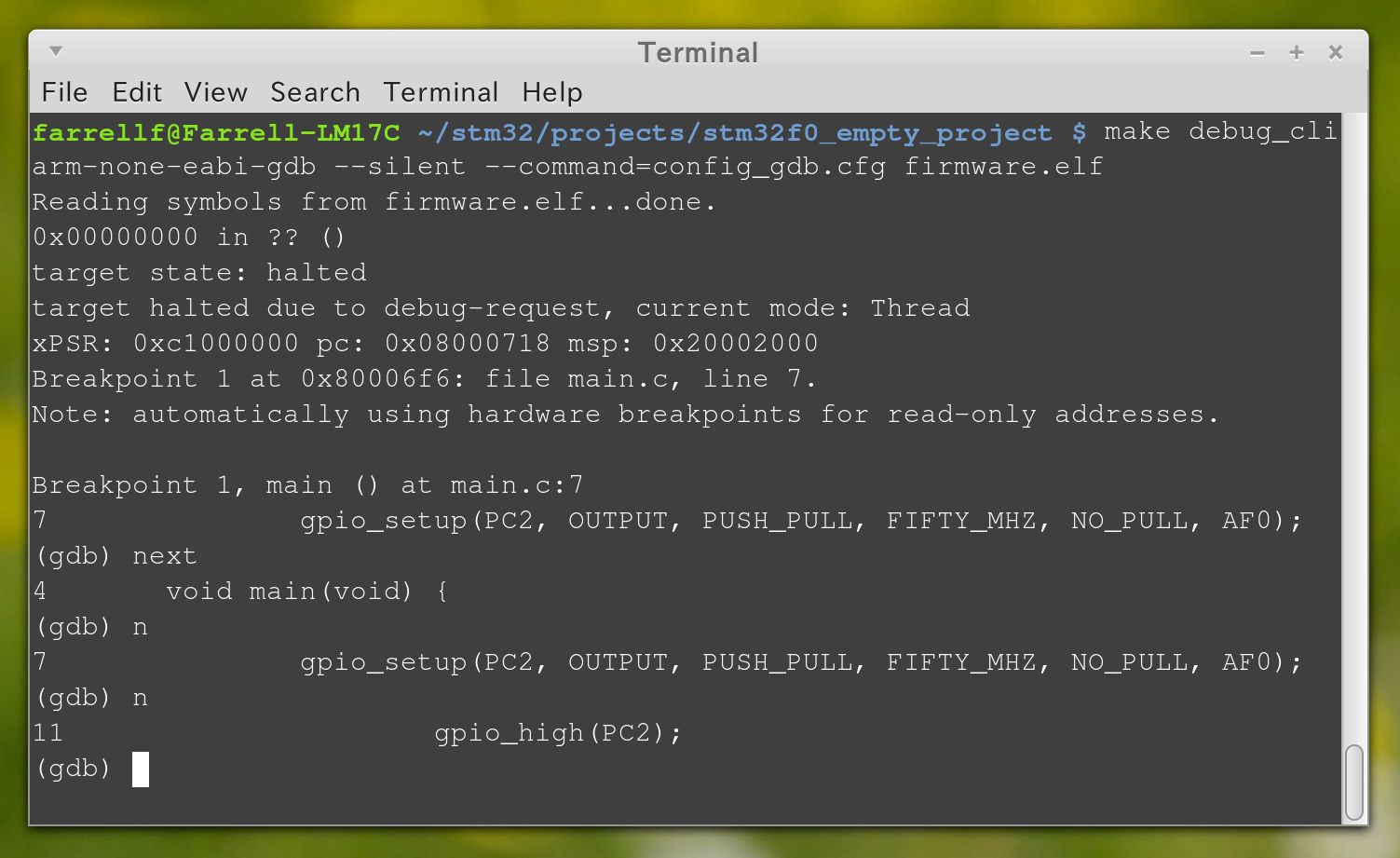
Debugging: From the Command Line

Command line debugging with this project is also really easy:

$ make debug_server $ make debug_cli

make debug_server will have to stay running for the duration of the debugging process, so run it in a separate terminal window. After closing gdb you can close the server with Ctrl-C.

RS232 Telemetry Viewer

While developing my balancing robot I needed to visualize certain variables. Being able to monitor angles, velocities and feedback loop factors made it easier to tune the control loop and verify the correct functioning of my sensors. I wrote the program in Java, utilizing the Swing and RXTX libraries.

Current values for each data point are shown with the sliders and text labels. Clicking on a data point will bring up a new window that shows the history of that data point in the form of a line graph. Multiple line graph windows can be used to track the history of several items at once.

The source code can be downloaded as a zip file, or accessed through my RS232 Telemetry Viewer repository on GitHub. To run the code you will need to install the RXTX library.

The code is split into eight classes: Main, Database, TelemetryGUI, ConfigurationLoader, SerialConfigPanel, SerialPortListener, BallPanel and LineGraph. The TelemetryGUI class has two inner classes: TelemetryGroup and TelemetryItem.

Main simply creates an instance of the Database and TelemetryGUI classes.

Database is used to store the history of values for each data point.

TelemetryGUI configures the main window and creates an instance of the ConfigurationLoader to read the configuration text file and make the corresponding panels. A BallPanel is used to visualize the robot's pitch and yaw angles. A SerialConfigPanel shows the available serial ports and baud rates, and allows the user to establish a connection with the selected port.

SerialPortListener is used to spawn a new thread that monitors the RS232 link, interprets incoming text, and populates the database with new values.

LineGraph is a window that shows the recent history of an item in the form of a constantly updating line graph.

Here's a video clip of me testing an early version of this program with my robot back in December 2013:

Balancing Robot Firmware

I'm releasing the firmware for my balancing robot into the public domain. Use it however you wish. The code is rather specific to my choice in microcontroller and sensors, but it might still be helpful to those working on their own robots.

Most of the work takes place in two files: main.c and isrs.c.

The main() function does all of the initialization work, then enters an infinite loop that constantly streams telemetry data out via RS232.

The interrupt service routines in isrs.c are where all of the “real work” is done. That's where the new values from all sensors are read, steering and throttle commands are received from the CC2500-based 2.4GHz transmitter, and the motor PWM values are adjusted based on a PID control loop.

I have amassed a small collection of reusable code while working on various projects with the STM32F0 microcontroller. This collection of code is not polished enough for sharing, but since it was used in this project I am including it anyway. It's in the /f0lib/ directory and should be used with caution. Be sure to read the function implementations before reusing the code in your own projects. The code in /f0lib/ was only written with my particular use cases in mind.

The firmware can be downloaded as a zip file, or accessed through my Balancing Robot repository on GitHub. Have fun!

Video clips and more photos are in my previous post from May 18th.

Balancing Robot

Over a year ago I started to work on a small balancing robot. Between learning more about communication protocols and feedback loops I also had periods of schoolwork that kept me from this hobby. In the end my little robot was balancing on his own and I could send steering and throttle commands wirelessly.

This project marked many firsts for me. It was the first time I made use of my microcontroller's I2C, UART and ADC peripherals. It was the first time I heard about PID control loops. It was also the first time I used an RF module to communicate wirelessly.

As I progressed I took several photos and video clips when milestones were met.

During the planning stage I selected a 3-axis gyro and a 3-axis accelerometer. I settled on STM's L3GD20 and LSM303DLHC devices. I laid out and etched a breakout board for them, then wrote a little Hello World test to draw bar graphs for the gyro readouts.

I decided to use a pair of RC hobby servos to power the robot. I removed the feedback potentiometers and modified the output gears to allow for continuous rotation. Some steering wheels from RC hobby transmitters were initially used as the wheels. The robot frame was constructed with some brass square tubing cut to length and soldered together. A gimbal was used for steering and throttle inputs since I didn't want to dive into the 2.4GHz module's lengthy datasheet until the end.

The wheels quickly proved to be a problem. While they had great traction, their diameter was far too small. The robot could easily drift a little too much, and the servos at full power couldn't spin fast enough to overcome the drifting.

I went with larger diameter wheels, making it much easier for the robot to balance:

The robot was actually drivable at this point. I added optical wheel encoders to make it easier to sense when the robot started to drift off course. Without the encoders the robot could drift if the driving surface wasn't perfectly level. By now the little guy was a mess of breakout boards, flying wires and extensions.

To clean up the mess I designed and etched a PCB specifically for this robot. I incorporated dual H-Bridges on the PCB to give better control over the motors. Previously I had just generated servo signals and let the servos' PCBs control the motors. This mostly worked, but as the servo PCBs came up to temperature the signal center point would drift slightly. This meant that after about a minute of use the robot would effectively have a bit of steering and throttle applied.

I finished by designing and etching a PCB for the transmitter. That was shown in my earlier post about solder masks. A little tuning of the PID control loop brought everything together and I was done. I'll post the firmware in a few days after doing the last bits of clean up and documentation.

< Prev  4  Next >